On the Construction of Telescopes with Silvered Glass
Part 2

Optical Examination of Concave Surfaces
Three Different Procedures
Positive and Negative Aberration
      When a mirror does not produce good images, normally one simply rejects the surface without seeking to find out exactly where its faults lie. The surface is worked over again, and the work is repeated to the point where the mirror is deemed good enough. But on this point -i.e., what is success -opinions quite often differ. However, there are ways to tell if a surface has in fact reached a figure which is suited to the requirements for it to function.
      Let us suppose that we need to verify a concave, spherical mirror. This sort of mirror has the property of returning, without distortion, all rays of light that originate from the center of curvature, back to that same point. Distributed in space around that center, and at a very small distance from it, is an infinite number of pairs of conjugate foci, which enjoy - as far as can be detected - the same property. Now imagine a point of light located right next to the center of curvature. On the exact other side of that center, an image of that point of light will be formed, which we can observe with a low-power microscope. If the surface is perfect, then the point is well-defend, the image is clear, and is surrounded by diffraction rings. Also, the changes which it undergoes on one side and the other of the focal point, when one moves the microscope in and out of focus, are symmetrical [i.e. identical]. Such are the characteristics of a perfect focus formed by a cone of rays which all cross at the same point in space.
      If the image is not perfect, then when one attempts to bring the light to a focus, one cannot produce as clear an image. However, at some point the light concentrates to a maximum, and we can consider that to be the true focal point. If the image at that point is round, then we can conclude that the surface of the mirror, while not being exactly spherical, is at least a surface of revolution around a center. We can then be certain that when one moves to one side or the other of the point of best focus, we will observe different and complementary patterns: light and dark concentric rings [lit. condensations and rarefactions of light] will appear in a complementary manner on either side of the focal point. These changes indicate variations in the radius of curvature in the corresponding zones of the reflecting surface.
      A bit of thought will easily show in which directions those changes occur. When we move the eyepiece forward, and pass in front of the focal point, we observe the status of the bundle of rays ahead of its point of convergence. If this point is not the same for all the various concentric zones on the mirror surface, then those zones which have the shortest focal length will produce, on the observing plane, a premature intensification of light, indicating a too-short focal length. The exact opposite occurs for zones where the focal length is too long. If we now draw the microscope backwards in such a way as to observe the status of the bundle of rays after they cross each other, we should observe the exact opposite phenomena, and these should bring us to the same conclusions.
      Generally, with well-made surfaces, the deformations in shape take the form of gradual changes in the radius of curvature, which varies slowly and in small amounts and in a uniform direction from the center to the circumference of the mirror. Also, the two symmetric images observed to one side and the other of focus normally appear as circles, one with the brighter part towards the center and the other one towards the periphery.
      When the surface being examined is not one of revolution, one is warned of that fact by the deformation of the images, which are not round, but divide themselves into unequal subdivisions.
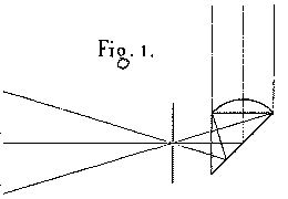
      To perform this experiment, we create a point source of light to be used as the origin of the rays to be emitted. We glue a short-focal-length plano-convex lens onto one of the two identical faces of a small, totally-reflecting right angle prism (Plate 1, figure 1). A lamp flame is placed 20 to 30 cm away from the axis of the experiment, and its horizontal rays illuminate this lens, which is perpendicular to those rays of light. The converging rays of light are completely reflected by the hypotenuse surface of the prism. These rays then form, outside of the prism, an image of the flame on a small opaque screen. This screen is pierced by a pinhole, which we can consider to be a point. This screen is placed near the center of curvature of the mirror and is so oriented as to fully illuminate the mirror. A microscope is used to examine the conjugate focus.
      This method of examining concave surfaces is sufficiently rigorous to find the smallest imperfections. But it works best of all when it is necessary to decide whether the mirror surface is one of revolution [i.e., is not astigmatic - trans.]. However, when one wants to perform local refiguring of the mirror, it is useful to find more precise information on the variations in the radius of curvature. In such a case, it is time to use a second method, based on an entirely different principle.
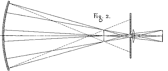
      In the region around the center of curvature, we set up two straight lines, very close to each other, such as the two edges of a metal wire one millimeter in diameter. This object is illuminated by an oblique mirror, so that it is projected onto a lighted background as seen from any point on the surface of the objective mirror. The image produced is observed either with the naked eye, or, better yet, by means of a small lens, through a diaphragm with an opening of 1.5 millimeter. In this situation, the object appears as a lighted disk, whose size corresponds to the opening of the mirror. And if the edges are not straight lines, then the inflections that appear will help us to characterize the variations in the radius of curvature. To help us understand why this is true, simply make a drawing tracing the paths of the rays of light from the surface of the mirror to the focal plane of the lens (figure 2). Then you will see how the little pinhole, by eliminating most of the rays which formed the direct image i, has the effect of composing the transmitted image i' with the rays reflected by different parts of the mirror. (This sounds a lot like a primitive version of the Ronchi Grating with only two lines in it - Bob)
      Now, if the radius of curvature varies from one zone to the other, then image i will not be entirely complete, and image i' will be formed at each of its points by partial ray bundles with different foci. The latter image will curve in space, and the angles subtended in the observer's eye by the different parts of the image will not be proportional to the corresponding parts of the object. In a word, this image will appear deformed. One will see contractions and dilations, representing reductions or increases in the radius of curvature from the corresponding parts of the mirror. [Note: the last two paragraphs have confused at least two translators! -- trans.](Pretty close to the lateral waviness seen with a Ronchigram when the surface of the mirror is not a proper surface but rather zoney in it's appearance - Bob)
      If one wants to inspect the entire mirror with a single glance, it is necessary to take for viewing object a regular grid network marked with congruent squares. The image of this object very readily reveals any deformations, wherever they may appear. (Basically a two dimensional Ronchi Test rather than the single dimension that we presently use - Bob)
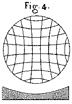
      Let us assume that we have the most usual type of situation, namely that the mirror is exactly spherical in its central region, but varies towards its circumference by a gradual increase in the radius of curvature. If we submit such a mirror to the second examination process we just described, then we will see an image in which all the lines of the grid will be curved as in figure 4, where the lines bow inwards and their concavity faces outwards. The cells of the grid increase their are as one proceeds from the center to the edge, and they change in the same direction as does the radius of curvature of the corresponding sections of the mirror surface.
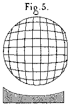
      An opposite deformation of the mirror, wherein the edges of the mirror slant inwards too quickly, produces a reversal of the curvature of the lines of the grid pattern, as shown in figure 5. The result is that the areas of the cells in the image get smaller as one approaches the edges of the field. Once again, the changes in the areas of the cells of the grid correspond to the changes in the radius of curvature.
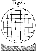
      For a final example, it often happens that the edges of a mirror are reduced below the level of a sphere, while the surface of the mirror also presents a raised central region, bounded all around by a sort of circular furrow. In this case, the radius of curvature changes first in one direction, and then in the opposite direction as one proceeds from the center to the edge. This situation will reveal itself very clearly via the sinusoidity (probably a more literal word here would be waviness - Bob) of the lines of the grid (see figure 6). This arrangement produces an analogous variation in the areas of the cells of the grid.
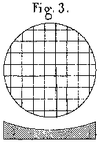
      We have taken care to reproduce, on the plate with the diagrams referred to earlier, showing the observed images, enormously exaggerated profiles of the deformed mirror surfaces. Thus, this second method of examination of mirror surfaces gives information that is very definitive and very easy to interpret. In the case where the lines produced appear to be more-or-less straight (figure 3), one cannot be sure whether or not one has in fact obtained a perfect surface. For that, the mirror will need to undergo the rigorous examination of a third and final method.
      As with the first method, we need to have a point source of light close to the center of curvature, in such a way as to not mask the rays of light returning from the mirror surface. After crossing each other, these rays of light form a divergent cone into which the observer places his or her eye. Then one moves the eye forward, in front of the focal point, until the entire surface of the mirror appears illuminated. Then, using a mask with one straight edge, we intercept, or cut into, the image until it disappears completely. This maneuver makes the eye of the observer see a progressive extinction of the reflection from the mirror. In the case of a perfectly spherical mirror, the entire surface will be fully and equally illuminated until the final instant (when the illumination goes away. - Bob). If the mirror is not completely spherical, the extinction of the light is not simultaneous over the entire surface of the mirror. From the contrast of the shadows and lighted areas, the observer can perceive, in a sort of chiaroscuro (def. treatment of light and dark in a drawing - basically used as from the timeframe of the work artists were doing in the 1850's - Bob) effect, an exaggerated impression of hills and valleys on the mirror, showing what needs to be done to obtain a spherical surface. This is the effect that must needs result from the paths of the rays converging more or less precisely at a common focal point.
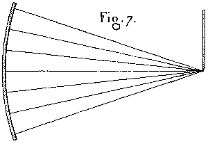
      In the theoretical case of a perfect spherical surface, the image of the luminous point is a disk that is sharply defined and which includes all of the reflected rays. Once this is masked by our straight-edge, no light at all reaches the eye of the observer (figure 7). But insofar as this disk passes the mask at all, then, since each of its points contains rays reflected by the entire mirror surface, that surface is more or less illuminated and displays a uniform brilliance to the observer.
      Let us suppose that the mirror surface is defective: the image of the point, instead of having a clear edge, will be surrounded by a luminous aureole, or ring, formed by the aberrating rays. When the correct image is masked by our knife-edge, then these rays, passing beyond, will proceed to the eye of the observer and will reveal the elements of the mirror surface that do not present themselves below the desired incidence.
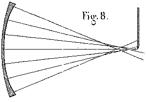
      In figure 8, which represents the effects of a mirror surface with the edges raised too high, we see clearly that the knife-edge screen -- cutting the central ray forming the image - allows the rays that come from the raised edge to pass through. Consequently, at the moment when the main central ray bundle is being progressively cut off, the upper (or right-hand) edge will appear brightly lit and the opposite edge will already be blackened out, while the central region will undergo a uniform, slow shadowing-out.
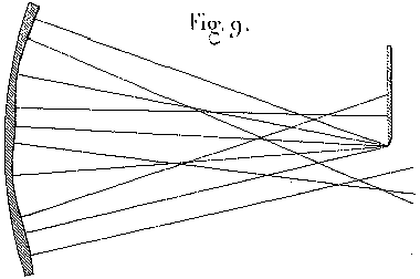
      In general, if the surface being examined in this way suffers from hills and depressions distributed in some random manner, as in figure 9, all the slope faces of the hills and valleys that face towards the knife-edge screen will appear to be black, and all the slope faces that are inclined in the opposite direction will be illuminated. Thus, the appearance of such a surface will be the same as that of a matte (or more literally - 3 dimensional - Bob) surface that presents, with an extreme degree of exaggeration, peaks and troughs distributed in a similar manner, and which appears to be illuminated by an oblique light source placed on the opposite side of our knife-edge screen.
      It is important to remember this rule if one wants to avoid all uncertainties in interpreting the observed results, for it often happens that the hills and the valleys seem to the observer to switch places, in a sort of optical illusion that is independent of the conscious mind. However, no matter one thinks one perceives, one can be sure to avoid this error of sign or direction as long as one takes into account the position of the knife-edge mask and that one uses that information to interpret correctly the disposition of the lighted and shadowed points.
      In summary, we have now three procedures we can use to verify the configuration of concave reflecting surfaces. The first method is based on the microscopic examination of the image of a point of light, and is particularly applicable in the case where one wants to determine whether the mirror surface is one of revolution. The second, which operates by elimination, using that a lens that is very narrowly stopped-down, applies to the observation of the image of a network of square cells. This method has most of all the power to show the variations in the radius of curvature at different points on the surface. The third method, the most sensitive of all, relies on the direct observation of the surface with the naked eye of rays of light coming to a focus and passing by the edge an opaque knife-edge mask.
      Observing with a microscope the image of a point; studying via a stopped-down lens the deformations in a grid; and looking at the surface with the naked eye and with rays of light that escape being cut off - these are the artifices that we call upon, one checking the other, to furnish all the desired information on the conformation of optical surfaces.
      Up until now we have assumed that these procedures can only be applied to spherical surfaces, and are limited in their application to the cases where the conjugate foci are very close to the center of curvature. With these restrictions, explaining them was clearer and easier. However, considering them from another point of view, these procedures take on a much more general nature, which renders them even more important.
      Making an abstraction of the mirror surface so as to consider only the reflected bundle of rays, the information furnished by these examination procedures can be applied to the bundle itself, and the characteristics which have been noted as the attributes of a spherical surface become in essence the properties of a bundle of rays which are exactly one of the conic sections.
      Now, inasmuch as the quality of the images depends precisely on the final convergence of the rays of light, these instruments, no matter what type they may be, fall under the aegis of these very same testing methods. Thus, we are no longer required to observe a mirror at its center of curvature, and since our proposed goal is to construct telescopes to observe objects located at infinity, we will take the concave mirror as it leaves the hands of the artisan, and we will lead it, via a series of transformations, to a figure which will make it suitable to function on celestial bodies.
      This glass mirror, without even being silvered, reflects enough light so that it can undergo all three examinations described earlier. We observe it close to the center of curvature. If it is spherical, the image of the point of light is round, clear, and distinct; the lines of the grid are straight; and we can produce a simultaneous extinction of light over the entire surface.
      Once this status is confirmed, we move our source object closer to the surface of the mirror. The image naturally moves farther away from the surface, and the distance between the two conjugate foci increases, as required by the fact that in an ellipsoid of revolution there must be perfect convergence of the reflected rays at the second focus. However, since the surface has in fact remained spherical, the rays emitted from one point will not actually all cross at a single point. We confirm, by the use of the three testing methods, that there exists an aberration, such that the various sections of the mirror have shorter and shorter focal lengths the farther they are away from the center of the mirror.
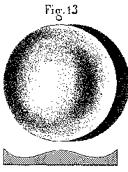
      The image of the point of light, examined under a microscope, begins to be surrounded by a halo of aberration. When we change the focus of the microscope, we see this image degenerate, on one side and the other of the focal plane, into two complementary images, of which one, closer to the mirror, presents on its periphery an accumulation of light, and the other, farther from the surface, has the opposite arrangement. The lines of the grid begin to curve in such a way as to present their convexity towards the outside, as we see in figure 5. Also, the extinction of the image by the knife-edge mask produces, on the surface of the mirror, an unequal distribution of light, as we see in figure 13, which appears like a raised center and raised edges, with a circular depressed area between the two.
      From all of this information, we conclude that the surface of the mirror is not one that would match the present state of conjugate foci [i.e., an ellipsoid - trans.] and that it differs from that in such a way that the radius of curvature is too short, and becomes more so as one moves away from the central part of the mirror. We now see clearly the modifications necessary to perform on this surface in order to bring it to a better state: we need to perform local refiguring so as to re-establish the lacking relationships among the radii of curvature. We will see later on that there is an infinite variety of methods of performing this refiguring.
      Let us continue. In other words, let us bring the object closer to the mirror, and at the same time we will push the image farther and farther away from the mirror. The aberration will increase, along with the phenomena that reveal the magnitude and direction thereof. It becomes clear that for a spherical surface the aberrations increase along with the distance between the two conjugate foci.
      But let us suppose that, when leaving the center of curvature and before passing from one station to the other, we were able to master the phenomena of aberration by performing the local refiguring that is suggested by our examination procedure. In that case, the figure of the mirror, which was originally spherical, will be gradually modified by a series of light refiguring operations. These changes will make the surface pass through a series of ellipsoidal figures, ending up, at the limit, with a paraboloidal surface. Such is the method we have followed, with success, to obtain large-aperture mirrors that give good images, without aberration, of images situated at infinity.
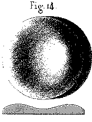
      Once we have succeeded in removing all aberrations for the particular case of conjugate foci, and we have returned to one of the positions we were in previously, we observe all of the phenomena returning, but in reverse order, which gives evidence of an aberration in the cone of the converging rays. The image of the point of light, surrounded even at the focus by a luminous halo, degenerates, as one pulls back the ocular microscope towards the observer, into a bright ring of light with a center that is more or less dark. The lines of the image of the grid appear curved with their concavity facing outwards (figure 4). The surface, viewed with the knife-edge mask, appears with a trough in the central region and with the outside edges turned down (fig. 14). In a word, all the phenomena appear to be the opposite of those which one observes on a spherical surface tested at a point outside the center of curvature.
      {This suggests an interesting experiment: one can bring in the knife-edge from the opposite side in testing a sphere at a particular set of conjugates and see the exact result of testing an ellipsoid properly figured for these conjugates at its center of curvature. This type of experiment has many possibilities in testing. Many variations suggest themselves.}
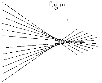
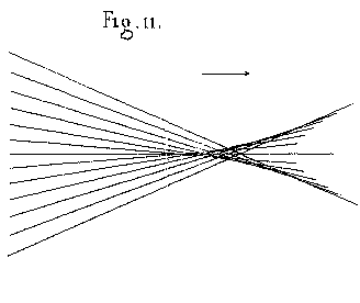
      If we agree to consider as positive the type of aberration which results the most often from the disproportionate extension of spherical surfaces, then we will denote as negative the aberration in the opposite direction which results from an exaggerated or inopportune correction of a spherical figure. But, if we only consider the ray bundle as a whole independent of the apparatus that makes it converge, we can agree to denote as a positive aberration the arrangement of a bundle of rays wherein the central ones converge last of all. In this case the caustic (see figure 10) formed by the series of crossing rays has its vertex turned towards the side where the light is heading. By contrast, we will call a negative aberration the opposite arrangement, wherein the central parts of the ray bundle converge first, and wherein the caustic has a vertex pointing towards the mirror, as in figure 11.
      These two states of the bundle of light rays correspond to two opposite appearances. Since one given ellipsoidal surface can produce either positive or negative aberrations, depending on whether it is functioning for foci located inside or outside the limits corresponding to its own foci, we can see that a single surface can produce, via the third examination procedure, two opposite appearances. To understand this fully, it is important to note what is the geometric direction of the figure that appears in such a situation.
      Recall this: given that a surface functions in such a way as to return towards the observer a ray bundle that is free of any aberration, then that surface, no matter what it might be, when examined by method #3, will appear uniformly illuminated as if it was a plane surface. Thus, if subsequent changes occur that disturb the convergence of the rays, then the appearance of the surface will be modified so that it will appear as different from a plane surface as the altered surface differs from the correct figure. In other words, the relief of the solid which displays itself in such a case, instead of revealing the true surface of the mirror, show us the figure of the solid that is superimposed upon the correct surface.
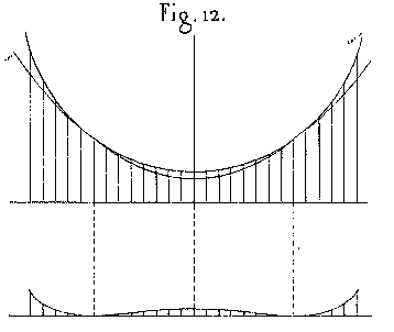
      Let us suppose, for example, that a spherical surface is examined in circumstances where it should present an ellipsoidal figure. That is to say that instead of the correct figure s (shown in figure 12) we substitute figure s' which is not correctly figured. To have an idea of the appearance which should result from this, let us put the circle and the ellipse on the same set of coordinates, and then let us construct the curve given by the changes in the differences in the y-coordinates corresponding to the same x-coordinates. This curve, which is of the fourth degree, is in fact the one which, if we imagine it rotated around the y-axis, would generate a surface that matches what we see in black-and-white shadows (figures 13 or 14) on a mirror that is examined by the third method, and when this mirror has a central zone that is a conic section, and when it has been verified as being outside the conditions defined by the positions of its own foci.
      We can also see that in this figure there is an inversion of the hills and valleys, depending on whether the actual surface of the mirror is inside of or outside of the theoretical surface corresponding to the positions occupied in space by the object and the image. In this way, we begin to understand the various images presented by an ellipsoidal mirror, as these images are progressively and continuously varied, when we consider all the distances where the image that results from the convergence of the reflected rays can be formed.
      Of the three testing methods which have been described in this essay, one alone, if required, could be sufficient to guide the hand which must perform the local refiguring on the mirror and cause it to pass through all of the various ellipsoids to culminate in a final parabolic surface. But if we use them all together, we are more assured of avoiding false maneuvers. Also, the various testing methods complement, rather than supplant, each other. Experience has shown many times that when all three methods are united in agreement that a particular surface has no defects, then the optical results of that mirror attain such a degree of perfection that nothing more could be desired. One could even knowingly permit a few small undulations to remain that can be seen in the third method, without the optical results of the mirror being at all noticeably different. This seems to show that sort of test achieves, regarding optical surfaces, a sort of super-sensitive reaction. The difficulty is now no longer to find the imperfections in the work on the surfaces, but to address the surface of the glass via an agent that will suffice to remove the minuscule quantities of glass which we need to remove.
Go to Another place
Previous Page Index Page Next Page