Some Notes on the Mobsby Null Test
One of the interesting tests for aspheric surfaces that has been figured out is the Mobsby Null Test. This test is a variation of the Ronchi Grating Test in that a grating is made that compensates for the curvature of the Ronchi lines on the mirror image that are caused by the aspheric surface under test. The calculations are to bend the lines of the grating so that when the test is done, you see the lines as straight if the aspheric curvature of the mirror is correct. The only restriction for the test is that the test is specific for a particular focal length and size of mirror. If you are interested in doing several mirrors of the same focal length, this is a nice test for you as it is an easy test to run on the mirror and is accurate in determining if the mirror is good or not. If you make the grating large enough and you apply circles of differing radius, you can test differing diameters, one for each size you have put on the grating.
An Introduction to the test.
The article by A D. Malaraca and Cornejo in Applied Optics Vol 13-8 is the source for this article.
The Ronchi test has been popular for many years for testing spherical surfaces as the test produces nice straight lines which are easy to understand. This method has also been used for testing aspherical surfaces but, as the fringes thus produced at the detector are not straight, their shapes must be calculated to get the correct surface shape. However, this procedure does not give accurate results mainly because of the following reasons:
- The technician figuring the surfaces has no easy way to match a curved fringe to a theoretical curve line. I would be a lot simpler to match a straight fringe to a straight line.
- Since the fringes are curved, the diffraction effects tend to diffuse the fringes, making the measuring procedure very uncertain and inaccurate.
The above disadvantages can be overcome by means of a special kind of Ronchi ruling with curved lines, the curvature of which compensates for the asphericity of the surface to produce straight fringes. The ruling is calculated such that the straight fringes on the surface are also constant in thickness
The Theory.
The ruling is computed using the following procedure:
- The transverse aberration TA(r) curve is computed at the approximate place where the ruling is to be placed, using a ray tracing program, as shown in Fig. 1. The ruling should be inside of the shortest focus of the surface in order to avoid closed loop lines on the ruling. Five points must be determined as shown in Fig2.
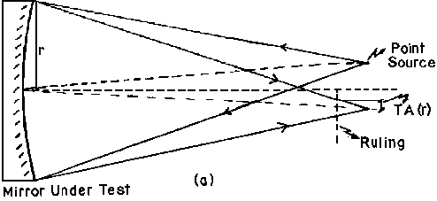
Fig.1
General layout of the test.
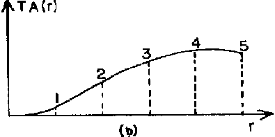
Fig. 2
5 points on the shape of the surface.
- A system of five linear simultaneous equations then has to be solved in order to determine the coefficients of the following aberration polynomial:
TA(r) = air + a3r3 + a5r5 + a9r9 - - - Eq. 1
The value obtained for the coefficient a1 depends on the position of the ruling and not on the asphericity of the mirror. Therefore, changing the value a1 is the equivalent to changing the position of the ruling. Since the exact desired position for the ruling still to be determined, the coefficient a1 may be considered to be unknown.
- The shape of a curved line on the ruling required for a given straight fringe on the surface is now computed using the following relation obtained from Fig. 2:
cosØ = Xs/r = XR/TA(r) - - - Eq. 2
where Xs and Ys and r are measured over the aspheric surface and XR , YR and TA(r) are measured on the ruling. From Eq. (2) we obtain:
XR = Xs{[Ta(r)]/r} - - - Eq. 3
and similarly:
YR = Ys{[Ta(r)]/r} - - - Eq. 4
Then, for a given value of Xs, many different equidistant values of Ys are assigned and the corresponding value of r is calculated using
r = (Xs2 +(Ys2)1/2 - - - Eq. 5
The value of a1 is determined by means of this relation:
a1 = PR/PS - - Eq. 6
where PR is the period of the ruling in it's central region assuming that a line goes through the origin and PS is the separation between fringes on the mirror.
- Next TA(r) is calculated from Eq. 1 and XR and YR from Eqs. (3) and (4). The values assigned to Xs are on both edges of the desired fringe in order to obtain both edges of the curved line on the ruling.
In Fig. 3 the calculated ruling is shown for a paraboloid with a diameter of 30cm and a radius of curvature of 202cm. Figure 4 shows the fringe pattern obtained with the normal Ronchi Test using a ruling of 32 lines/cm. Figure 5 shows the Null Ronchi Test using a calculated ruling with the same central period, 32 lines/cm. Please notice that the fringes, in addition to being straight, are better defined in the null Ronchi Test.
The ruling must be positioned very precisely when the test is made because the aspericity compensation depends very critically on that position. This is easily done if a circle is drawn on the ruling so that it's projection on the mirror surface coincides with the outer edge of that surface. The diameter of this circle can easily be computed.
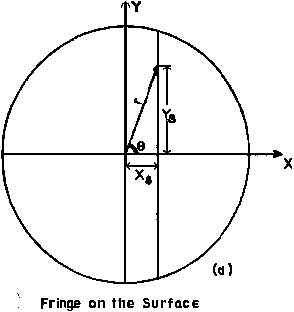
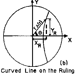
Fig. 3					Fig. 4
	Fringe indication		 Where the lines are measured
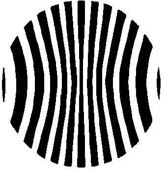
Fig. 5
Computed grating.
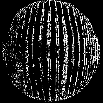
Fig. 6
Photo of a normal Ronchi Grating Test.
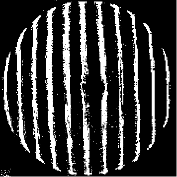
Fig. 7
Photo of Mobsby Test on a mirror.
Conclusions to ponder
The theoretical sensitivity of this test is the same as that of the basic Ronchi Test but in practice the sensitivity is greater because of the greater simplicity in the matching process and the reduced diffusion of the fringe patterns.
This test has, however, the restriction that it must be performed with a monochromatic point source. A small gas laser is ideal for this purpose. The pictures shown in Figs. 4 and 5 were made with a He-Ne gas laser.
Further notes
The original article was, as noted above, originally in Applied Optics by Malaraca and Cornejo and Eliezr Jarn did the photos and drawings. I'd also like to thank Richard Schwartz and Micheal Lindner for putting up the GIF version so that I could do this article. The text is pretty much verbatim from the article.
I would also note that apparently a guy named Mobsby was the original thinker on the test and thus, it carries his name.
I have some software from Stillman and Diaz and that code is
here at this address. There is also another webpage on the Mobsby test with a different program (Windows program) written in C which may work better for some. At this time (Sept. 2001), I haven't heard any reports back about the success or failure of the test and would be interested hearing anybody's results from this or any other software on the Mobsby test.


